
Description
 HT12D – 212 Series Decoder IC
 HT12D – 212 Series Decoder IC
(RF Remote Control Decoder IC)
General Description
 General Description
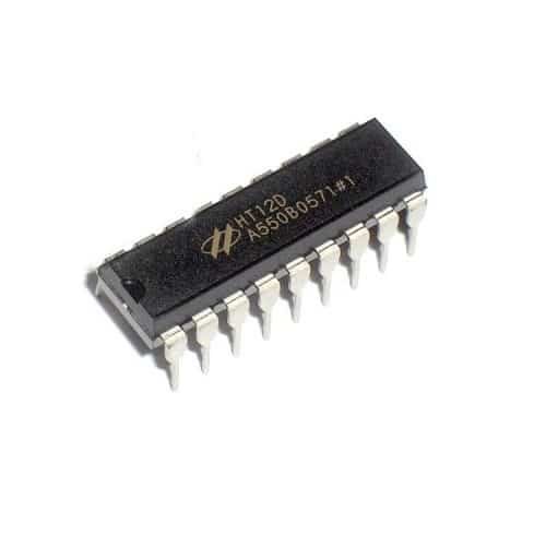
The HT12D is a 4-bit decoder IC designed for remote control systems using RF modules. It is usually paired with the HT12E (Encoder) to create simple wireless data communication systems. HT12D receives serial data and decodes it into parallel output, enabling control of remote devices.
It’s commonly used with 433MHz or 315MHz ASK/OOK RF modules.
Specifications
 Specifications
| Parameter | Value |
|---|---|
| Operating Voltage | 2.4V to 12V |
| Decoder Bits | 8 Address Bits + 4 Data Bits |
| Input Type | Serial Data from RF Module (DIN pin) |
| Output Type | 4-bit Parallel (D0–D3) |
| Valid Transmission | Indicated by VT (Valid Transmission) Pin |
| Typical Clock Frequency | 150kHz (set by external resistor) |
| Package | 18-pin DIP or SOP |
| Power Consumption | Very low (suitable for battery ops) |
| Data Rate | ~2Kbps (typical) |
| Decoding Time | ~50ms (depends on oscillator) |
Pin Configuration (18-pin DIP/SOP)
 Pin Configuration (18-pin DIP/SOP)
 +------------------+
A0 |1 18| A7
A1 |2 17| DIN (Data In)
A2 |3 16| VSS (GND)
A3 |4 15| D0 (Data Out 0)
A4 |5 14| D1
A5 |6 13| D2
A6 |7 12| D3
A7 |8 11| VT (Valid Transmission)
OSC1 |9 10| OSC2
+------------------+
Key Features
 Key Features
- Decodes 4-bit data from HT12E Encoder
- Valid Transmission output pin (VT) for signal indication
- 8 address bits for up to 256 address combinations
- Works with common 433MHz/315MHz RF modules
- Built-in oscillator with external resistor
- Very low power consumption
Typical Applications
 Typical Applications
- Remote control switches (lights, fans, pumps)
- Home automation systems
- Security systems and alarms
- RF-controlled toys
- Wireless data transfer systems
How It Works
 How It Works
- HT12E (Encoder) sends 12-bit data: 8-bit address + 4-bit data.
- HT12D (Decoder) compares received address with its own (set via A0–A7 pins).
- If address matches, it latches the 4-bit data onto output pins D0–D3.
- VT (Valid Transmission) pin goes HIGH during valid reception.
How to Use
 How to Use
- Set A0–A7 to match the transmitter (HT12E).
- Connect DIN to data pin of the RF receiver module.
- Attach a resistor (usually 51kΩ) between OSC1 and OSC2 to set internal clock.
- Monitor VT to confirm valid data.
- Use D0–D3 to control relays, LEDs, motors, etc.
Advantages
 Advantages
- Simple implementation for wireless remote systems
- Cost-effective and reliable
- Compatible with commonly available RF modules
- No microcontroller required
Limitations
 Limitations
- Fixed 4-bit data limit
- Not suitable for encrypted or high-speed data
- Range and reliability depend on RF module quality
Popular Part Numbers
 Popular Part Numbers
- HT12D – DIP-18
Reviews
There are no reviews yet.