
Description
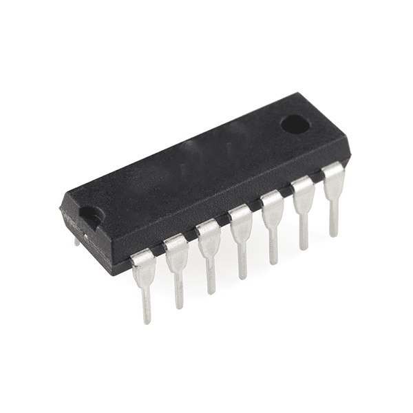
The 7420 is a Quad 2-input NAND Gate IC. It is a member of the 7400 series of integrated circuits and is commonly used in digital logic applications where NAND gates are required.
7420 IC Description:
The 7420 is a quad 2-input NAND gate IC, meaning it contains four independent NAND gates, each with two inputs. A NAND gate is a digital logic gate that produces an output which is the inverse (NOT) of the AND operation. It gives a logic LOW (0) output only when both inputs are HIGH (1), and in all other cases, it gives a HIGH (1) output.
Key Features:
- Quad 2-input NAND Gate: The IC contains four independent 2-input NAND gates.
- CMOS Technology: Like most devices in the 7400 series, the IC uses CMOS technology, which provides low power consumption and high noise immunity.
- Standard Logic Family: It is a part of the 7400 series, making it compatible with other TTL or CMOS logic ICs.
- Wide Voltage Range: It operates in a typical voltage range of 4.5V to 5.5V and can handle logic-level inputs and outputs.
Pin Configuration (14-pin package):
Here’s the standard pinout for the 7420 IC:
- Pin 1 (A1): Input 1 of the first NAND gate.
- Pin 2 (B1): Input 2 of the first NAND gate.
- Pin 3 (Y1): Output of the first NAND gate.
- Pin 4 (A2): Input 1 of the second NAND gate.
- Pin 5 (B2): Input 2 of the second NAND gate.
- Pin 6 (Y2): Output of the second NAND gate.
- Pin 7 (GND): Ground.
- Pin 8 (A3): Input 1 of the third NAND gate.
- Pin 9 (B3): Input 2 of the third NAND gate.
- Pin 10 (Y3): Output of the third NAND gate.
- Pin 11 (A4): Input 1 of the fourth NAND gate.
- Pin 12 (B4): Input 2 of the fourth NAND gate.
- Pin 13 (Y4): Output of the fourth NAND gate.
- Pin 14 (Vcc): Supply voltage (typically 5V).
How It Works:
Each of the four NAND gates in the 7420 IC has two inputs (A and B) and one output (Y). The output Y of each gate is determined by the following truth table:
| A (Input 1) | B (Input 2) | Y (Output) |
|---|---|---|
| 0 | 0 | 1 |
| 0 | 1 | 1 |
| 1 | 0 | 1 |
| 1 | 1 | 0 |
- The output Y will be 1 (HIGH) in all cases except when both A and B are 1, in which case Y will be 0 (LOW).
Applications:
- Digital Logic Circuits: NAND gates are universal gates, meaning they can be used to construct any other basic logic gate (AND, OR, NOT, XOR, etc.). The 7420 IC is often used in general-purpose digital logic circuits.
- Combinational Logic: In many applications, NAND gates are used for creating combinational logic circuits, such as adders, multiplexers, decoders, etc.
- Switching Circuits: NAND gates are widely used in circuits for switching purposes, such as in logic circuits that select between different signal paths based on control inputs.
- Timers and Oscillators: In combination with other gates and components, the 7420 can be used in timing and oscillator circuits.
- Signal Inversion: Since the NAND gate is the inverse of the AND gate, it can be used to invert signals or generate NOT logic when necessary.
Electrical Characteristics:
- Supply Voltage (Vcc): Typically 5V (with a range of 4.5V to 5.5V).
- Current Consumption: Like most CMOS logic ICs, the 7420 has low power consumption.
- Input Logic Levels: The logic levels for the inputs will typically range from 0V (for logic LOW) to Vcc (for logic HIGH), with appropriate input thresholds for a HIGH signal typically being 2V or higher.
- Output Logic Levels: The output will range from 0V (for LOW) to Vcc (for HIGH), suitable for driving logic-level circuits.
Example Application Circuit:
An example of using the 7420 could be in a pulse generator circuit. If you use a series of NAND gates with feedback loops and resistors, you can design a simple oscillator circuit. Similarly, you could use the gates for debouncing switches or creating timing circuits where logic signals need to be manipulated.
Reviews
There are no reviews yet.